The world’s Largest Sharp Brain Virtual Experts Marketplace Just a click Away
Levels Tought:
Elementary,Middle School,High School,College,University,PHD
| Teaching Since: | May 2017 |
| Last Sign in: | 398 Weeks Ago, 2 Days Ago |
| Questions Answered: | 66690 |
| Tutorials Posted: | 66688 |
MCS,PHD
Argosy University/ Phoniex University/
Nov-2005 - Oct-2011
Professor
Phoniex University
Oct-2001 - Nov-2016
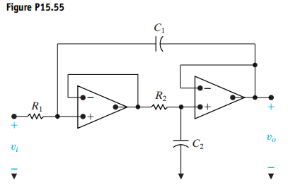
The fourth-order low-pass unity-gain Butterworth filter in Problem 15.55 is used in a system where the cutoff frequency is 3 kHz. The filter has 4.7 nF capacitors.
a) Specify the numerical values of and in each section of the filter.
b) Draw a circuit diagram of the filter and label all the components.
Problem 15.55
The purpose of this problem is to develop the design equations for the circuit in Fig. P15.55.
a) Based on a qualitative analysis, describe the type of filter implemented by the circuit.
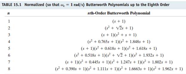
b) Verify the conclusion reached in (a) by deriving the transfer function
Write the transfer function in a form that makes it compatible with the entries in Table 15.1.
c) How many free choices are there in the selection of the circuit components?
d) Derive the expressions for the conductances
 ![]()


Â
 H-----------ell-----------o S-----------ir/-----------Mad-----------amT-----------han-----------k Y-----------ou -----------for----------- us-----------ing----------- ou-----------r w-----------ebs-----------ite----------- an-----------d a-----------cqu-----------isi-----------tio-----------n o-----------f m-----------y p-----------ost-----------ed -----------sol-----------uti-----------on.-----------Ple-----------ase----------- pi-----------ng -----------me -----------onc-----------hat----------- I -----------am -----------onl-----------ine----------- or----------- in-----------box----------- me----------- a -----------mes-----------sag-----------e I----------- wi-----------ll -----------be