
Maurice Tutor
$15/per page/Negotiable
Design a series RLC band pass filter using only three components from Appendix H that comes closest to meeting the filter specifications in Problem 14.27.
a) Draw your filter, labeling all component values and the input and output voltages.
b) Calculate the percent error in this new filter’s center frequency and quality factor when compared to the values specified in Problem 14.27.
Problem 14.27
Design a series RLC band pass filter using only three components from Appendix H that comes closest to meeting the filter specifications in Problem 14.25.
a) Draw your filter, labeling all component values and the input and output voltages.
b) Calculate the percent error in this new filter’s center frequency and quality factor when compared to the values specified in Problem 14.25.
Problem 14.25
Using a 50 nF capacitor in the band pass circuit shown in Fig. 14.22, design a filter with a quality factor of 5 and a center frequency of 20 krad/s.
a) Specify the numerical values of R and L.
b) Calculate the upper and lower cutoff frequencies in kilohertz.
c) Calculate the bandwidth in hertz.
Fig. 14.22
The input to the series RLC band pass filter designed in Problem 14.21 is 5cosŌČt V. Find the voltage drop across the resistor when
![]()  
 ![]()
Problem 14.21
Design a series RLC band pass filter (see Fig. 14.19[a]) with a quality of 8 and a center frequency of 50 krad/s. using a 0.01őľF capacitor
Fig. 14.19 (a)
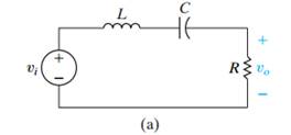
a) Draw your circuit, labeling the component values and output voltage.
b) For the filter in part (a), calculate the bandwidth and the values of the two cutoff frequencies.