Maurice Tutor

(5)

$15/per page/Negotiable

About Maurice Tutor

Levels Tought:
Elementary,Middle School,High School,College,University,PHD

Expertise:
Algebra,Applied Sciences See all
Algebra,Applied Sciences,Biology,Calculus,Chemistry,Economics,English,Essay writing,Geography,Geology,Health & Medical,Physics,Science Hide all
Teaching Since: May 2017
Last Sign in: 408 Weeks Ago
Questions Answered: 66690
Tutorials Posted: 66688

Education

  • MCS,PHD
    Argosy University/ Phoniex University/
    Nov-2005 - Oct-2011

Experience

  • Professor
    Phoniex University
    Oct-2001 - Nov-2016

Category > Management Posted 07 Feb 2018 My Price 5.00

no-load voltage

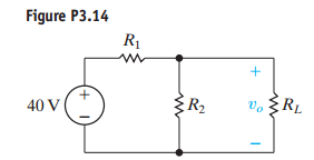
The no-load voltage in the voltage-divider circuit shown in Fig P3.14 is 8 V. The smallest load resistor that is ever connected to the divider is When the divider is loaded,  is not to drop below 7.5 V.

a) Design the divider circuit to meet the specifications just mentioned. Specify the numerical values of R1 and R2

b) Assume the power ratings of commercially available resistors are 1/16,1/8,1/4,1 and 2 W. What power rating would you specify?

Answers

(5)
Status NEW Posted 07 Feb 2018 07:02 PM My Price 5.00

Hel-----------lo -----------Sir-----------/Ma-----------dam-----------Tha-----------nk -----------You----------- fo-----------r u-----------sin-----------g o-----------ur -----------web-----------sit-----------e a-----------nd -----------acq-----------uis-----------iti-----------on -----------of -----------my -----------pos-----------ted----------- so-----------lut-----------ion-----------.Pl-----------eas-----------e p-----------ing----------- me----------- on-----------cha-----------t I----------- am----------- on-----------lin-----------e o-----------r i-----------nbo-----------x m-----------e a----------- me-----------ssa-----------ge -----------I w-----------ill----------- be-----------

Not Rated(0)